

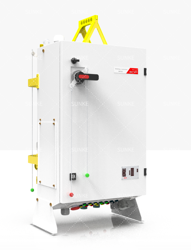
The central problem: what the monitor must actually prove
Engineers ask for a monitor but rarely define what “good weld” looks like on the shop floor. Start by stating the performance gaps you need to close: reduce rework, document weld strength, or detect intermittent failures on high-speed lines. The specification must tie directly to production conditions and to the specific resistance welding applications you run—cycle time, material stack-up, and accepted scrap rate. A monitor should answer a measurable question, not only log numbers.
Key electrical and mechanical metrics to specify
Define the exact signals the monitor must capture and how it reports them. Typical essentials include:- Weld current (peak and integrated energy).- Weld time and timing skew relative to actuator events.- Electrode force or displacement, including pre- and post-switch profiles.- Weld energy or Joules per weld, with configurable integration windows.- Waveform capture for transient analysis and event-triggered storage.State required sampling rates, resolution, and latency. Specify alarm thresholds as absolute values or statistical control limits. Precision matters: ±1% vs ±5% informs hardware choices.
Sensor placement, sampling strategy, and wire mesh welding nuances
Where you measure changes what you can prove. Current transformers on the secondary give circuit-level energy but lose local contact effects. Shunt resistors close to the weld head capture rapid transients. For electrode force use direct load cells at the ram, not inferred force from cylinder pressure. Wire mesh joints introduce different thermal paths and local contact points; monitor placement must resolve these local variations—see how manufacturers discuss wire mesh welding at major gatherings such as the WIRE trade fair in Düsseldorf for practical measurement approaches. Specify sampling that captures the fastest expected transient and allows post-event waveform analysis.
Common specification mistakes that create false confidence
Watch these traps:- Leaving “monitoring” vague. If you don’t name the metric, the vendor will pick one.- Overlooking electrode life. A monitor that ignores electrode degradation produces misleading pass results.- Specifying average values only. Short transients can destroy a weld; averages hide them.- Failing to require time-synced logging with production events. Separate event logs are useless for root cause.- Assuming one-size-fits-all thresholds. Materials, coating, and mesh geometry need distinct limits.
Trade-offs and alternatives — what a monitor replaces or complements
Decide whether the monitor is primary quality assurance or a diagnostic tool. Options:- Inline process monitors that reject parts in real time.- Offline destructive testing for periodic validation.- Vision or ultrasonic inspection as secondary verification.Each choice shifts costs and response time. Inline monitors reduce scrap after setup but require careful calibration and maintenance. Combine methods when material variability or safety-critical demands are high.
Practical specification checklist
Use this to finalize requirements:- Define the pass/fail metric and acceptable statistical limits.- List required signals, sampling rates, and waveform storage depth.- Require time-stamped synchronization with PLC or production database.- State environmental and EMI requirements for the plant.- Specify maintenance access, calibration intervals, and spare parts strategy.- Describe the expected operator workflow for alarms and data review.
Final synthesis
Specify a monitor to solve a concrete problem, not to collect comforting data. Clear metrics, correct sensor placement, and precise sampling turn a monitor into a tool that finds real defects and supports faster corrective action. When those elements are defined and aligned with production realities, a supplier like Sunke becomes a practical partner rather than a promise; the result is fewer surprises and weld records that match what your line actually produces.