

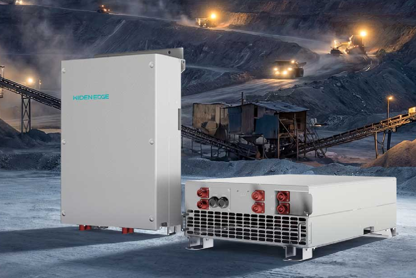
Problem — why these converters fail and what that means for your site
Small converter faults cascade fast: a failing fan or swollen capacitor can push a string offline and trigger alarms across a control room. Field experience commissioning modular inverter arrays in California shows thermal stress and improper grounding are common root causes. Address those root causes early — and verify telemetry — because larger systems like a 600kW energy storage inverter or a modular inverter depend on reliable DC-DC stages upstream. I write as an engineer who’s led inverter troubleshooting teams; this checklist focuses on actions that prevent repeat failures rather than temporary workarounds.
Monthly visual and basic electrical inspection
– Check enclosure seals and conduit entry points for moisture intrusion; wet wiring is a primary failure vector.
– Inspect heatsinks and fans: dust build-up > 3 mm or noisy bearings requires cleaning or fan replacement.
– Look for bulging or leaking capacitors and discolored PCB areas; mark and replace suspect parts.
– Verify all terminal torque values against manufacturer specs; loose DC bus connections create hotspots.
– Confirm status LEDs and alarm logs; clear non-persistent warnings after capturing a snapshot for trend analysis.
Quarterly firmware, telemetry, and control checks
– Validate firmware revision against the vendor’s latest release notes; prioritize releases that fix thermal or startup issues.
– Pull a telemetry window for at least 48 hours to detect recurring derates or transient voltage spikes.
– Test communication redundancy (CAN/RS485/Ethernet) and simulate a master controller failover to confirm that modular sections stay synchronized.
– Confirm SCADA tags map correctly and timestamps are aligned to avoid false event correlations.
Thermal and load validation (semiannual)
– Run an infrared scan under nominal load; log any >10 °C delta between similar components as actionable anomalies.
– Perform a staged load ramp to rated power while monitoring DC bus ripple and switching node temperatures; abnormal ripple often indicates aging capacitors or magnetics issues.
– Verify cooling airflow paths are unobstructed by cable bundles or field racks; incorrect airflow is a repeat offender.
Annual deep maintenance and component replacement window
– Replace electrolytic capacitors and any service-life items per the manufacturer’s mean time to end-of-life guidance; don’t wait for signs of failure.
– Remove and reseat connectors, then re-torque to spec; oxidation and micro-arcing develop silently.
– Re-certify insulation resistance on input/output isolation barriers and ground continuity with a megohmmeter.
– Review and archive a full system firmware and configuration snapshot so you can restore a tested state after a module swap.
Common pitfalls teams overlook
– Treating alarm clearances as fixes: alarms tell you what failed; they don’t fix the root cause.
– Skipping current harmonics checks: non-linear loads distort the DC bus and accelerate capacitor wear.
– Using generic replacement fans or capacitors: mechanical and ESR mismatches cause new failures.
– Ignoring transient suppression on long DC runs: additional surge protection often prevents repeated inverter trips.
Tools, documentation, and team practices that save site visits
– Keep a field kit: thermal camera, torque wrench set, ESR meter, megohmmeter, and a USB console cable.
– Maintain a change log with serial numbers for swapped modules and firmware versions tested on-site.
– Train at least two technicians per site on safe DC isolation procedures and module replacement steps to avoid single-point knowledge gaps.
– Standardize a “post-service” validation script: PV sweep, DC bus ripple measurement, and a 1-hour run to confirm stability before leaving the site.
Escalation criteria — when to call vendor support
– Repeated thermal anomalies after cleaning and component swaps.
– Intermittent comms failures that reappear after wiring checks (possible control ASIC fault).
– Unexplained derates or protective trips with nominal input voltages and currents.
– Visible PCB damage or combustion smells — stop, document, and involve manufacturer field service.
Final synthesis
Preventive maintenance fixes the predictable: torque, thermal control, component lifecycle, and telemetry discipline stop most outages. Keep checks regular, use the right spare parts, and document every swap so trend analysis reveals early degradation. For teams managing nested systems and larger storage interfaces, structured maintenance reduces emergency repairs and preserves operational capacity, and partners such as WidenEdge can provide modular support and parts coordination without replacing the hands-on practices described here.